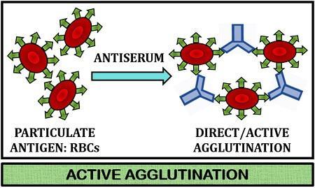
Agglutination is defined as the antigen-antibody reaction in which antibodies cross-link particulate antigens resulting in the visible clumping of particles. Antibodies that show such reactions are called agglutinins.
Agglutination reactions work on the principle of cross-linking of the polyvalent antigens. Following are the advantages of agglutination reactions:
easy to perform
require no expensive equipment, and
detects antibody concentrations as low as nanograms per milliliter.
Types of agglutination reactions:
Hemagglutination: type of agglutination reaction is routinely performed to type red blood cells (RBCs), wherein RBCs are mixed with antisera to the A or B blood-group antigens on a slide. The presence of antigen on the cell surface is proved by forming a visible clump on the slide. This RBC typing forms the basis for matching blood types for transfusions.
Bacterial Agglutination:
This type of agglutination reaction is performed to diagnose infection and provide a way to type bacteria. Any bacterial infection elicits the production of serum antibodies within the host.
These serum antibodies are specific for surface antigens on the bacterial cells, which bacterial agglutination reactions can detect.
Bacteria is added to the previously serial diluted array of tubes containing serum from a patient thought to be infected with a given bacterium. The last tube, which shows visible agglutination, reflects the serum antibody titre of the patient. Thus, the agglutinin titre is the reciprocal of the greatest serum dilution that elicits a positive agglutination reaction.
Active agglutination
In this type of agglutination, epitopes of interest are naturally found on a test particle, such as antigens found on RBCs, bacterial and fungal cells.
Examples –
Blood grouping and cross-matching
Widal test for diagnosis of typhoid fever
Brucella agglutination test for Brucellosis
Weil Felix test for Rickettsiosis
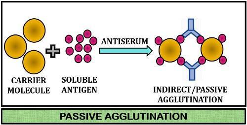
Passive agglutination:
Passive agglutination is useful when the epitope of interest does not occur naturally on the cells or particles to be agglutinated. The epitopes or soluble antigens are chemically fixed to carrier particles such as – latex, polystyrene, bentonite.
Passive agglutination is also useful when pathogen culture is not feasible, e.g., viral diseases.
Synthetic beads offer better consistency, uniformity, and stability. In addition, those agglutination reactions which employ synthetic beads are rapidly read within 3 to 5 minutes of mixing the beads with the test sample.
Article by- SAMPRATI PAREKH (MSIWM049).
References:
Cellular and Molecular Immunology by Abul K. Abbas – 7thEdition
Atopyis defined as the tendency of an individual to produce IgE antibodies in response to various environmental antigens and thus develop strong immediate hypersensitivity (allergic) responses. Individuals with allergies to environmental antigens (e.g., pollen, house dust) are atopic.
Localized anaphylaxis involves reactions limited to a specific target tissue or organ and often involves epithelial surfaces at the site of allergen entry. Atopy is thus defined as the tendency to manifest localized anaphylactic reactions, and this tendency is inherited.
Atopic allergies include a wide range of IgE-mediated disorders, including allergic rhinitis (hay fever), asthma, atopic dermatitis (eczema), and food allergies.
Allergic Rhinitis:
This is commonly known as “hay fever” and results from the reaction of airborne allergens with the sensitized mast cells in the conjunctivae and nasal mucosa, which induces the release of pharmacologically active mediators from mast cells. The mediators thus cause localized vasodilation and increased capillary permeability. The symptoms of allergic rhinitis usually include watery exudation of the conjunctivae, upper respiratory tract and nasal mucosa, and sneezing and coughing.
Asthma:
Asthma, a common manifestation of localized anaphylaxis, is triggered by degranulation of mast cells with the release of mediators, but instead of occurring in the nasal mucosa, the reaction develops in the lower respiratory tract. This results in the contraction of the bronchial smooth muscles and thus eventually leads to broncho-constriction.
Food Allergies:
A variety of foods can induce localized anaphylaxis in allergic individuals. In addition, localized smooth-muscle contraction and vasodilation can be induced by allergen cross-linking of IgE on mast cells along the upper or lower gastrointestinal tract resulting in symptoms such as vomiting or diarrhea.
Atopic Dermatitis:
Atopic dermatitis (allergic eczema) is an inflammatory disease of the skin frequently associated with a family history of atopy. This disease is observed most commonly among young children, often developing during infancy. Serum IgE levels are often elevated, and the allergic individual develops erythematous skin eruptions filled with pus.
Article by- SAMPRATI PAREKH (MSIWM049)
References:
Cellular and Molecular Immunology by Abul K. Abbas – 7thEdition
display MHC complexes in association with these peptide fragments of protein antigens on its surface to lymphocytes, and
provide signals that stimulate the proliferation and differentiation of the lymphocytes (co-stimulatory signal) are known as the antigen-presenting cells (APCs).
APCs are conventionally referred to as those cells which display antigens on their surface to the T lymphocytes. A dendritic cell is the major type of APC which is involved in initiating the T cell responses.
Macrophages and B cells also present antigens to the T lymphocytes but in different types of immune responses. The follicular dendritic cell, a specialized cell type, displays antigens to B lymphocytes during particular phases of humoral immune responses. APCs thus link responses of the innate immune system to responses of the adaptive immune system, and therefore they may be considered components of both systems.
Types of APCs:
Dendritic Cells
Dendritic cells form one of the most important APCs for activating naive T cells. These cells constitutively express a high level of class II MHC molecules and deliver a co-stimulatory activity and thus play major roles in innate responses to infections and link innate and adaptive immune responses.
Antigen-Presenting Cells for Effector T -Lymphocytes
In addition to dendritic cells; macrophages and B lymphocytes perform important antigen-presenting functions in CD4+ helper T cell-mediated immune responses.
Macrophages present antigen to helper T lymphocytes at the sites of infection, which leads to helper T cell activation and production of molecules that further activate the macrophages. These macrophages must be activated by phagocytosis of particulate antigens before expressing class II MHC molecules or the co-stimulatory B7 membrane molecule.
B cells present antigens to helper T cells in lymph nodes and spleen, a key step in the cooperation of helper T cells with B cells in humoral immune responses to protein antigens. These B cells constitutively express class II MHC molecules but must be activated before expressing the co-stimulatory B7 molecule.
Note: Cytotoxic T lymphocytes (CTLs) are effector CD8+ T cells that can recognize antigens on any nucleated cell and become activated to kill the cell. Thus, all nucleated cells are potentially APCs for CTLs.
Follicular Dendritic Cells:
Follicular dendritic cells (FDCs) are cells with membranous projections found intermingled in specialized collections of activated B cells, called germinal centers, in the lymphoid follicles of the lymph nodes, spleen, and mucosal lymphoid tissues.
Article by- SAMPRATI PAREKH (MSIWM049)
References:
Cellular and Molecular Immunology by Abul K. Abbas – 7thEdition
Pronunciation: ah-poh-toh’-sis: Greek, (1) apo- away from and (2) ptosis, a falling or dropping
‘Apoptosis’ has been derived from a Greek word that describes the falling of the leaves from a tree or petals from a flower. This term was coined to differentiate this form of programmed cell death from the accidental cell deaths caused by inflammation or injury (necrosis).
Introduction:
Programmed cell death is an active process, first described in 1972 and usually proceeds by a distinct series of cellular changes known as apoptosis.
Apoptosis is thus the genetically programmed death of cells that is both a natural development process and the body’s means of destroying abnormal or infected cells.
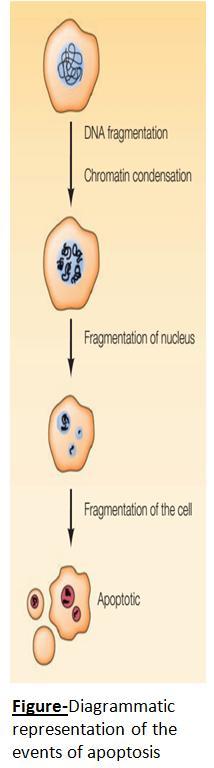
Events of apoptosis:
During apoptosis, firstly, as a result of cleavage between nucleosomes, chromosomal DNA fragmentation occurs.
↓
Following chromatin condensation, the cell shrinks in and breaks up into membrane-enclosed fragments known as apoptotic bodies.
↓
These apoptotic cells and cell fragments are efficiently recognized and phagocytosed by macrophages and the neighbouring cells, and thus, eventually, these cells, which die by apoptosis, are rapidly removed from tissues.
This removal of the apoptotic cells from the tissues is mediated by the expression of certain signals on the cell surface. These signals are generally known as the “eat me” and include phosphatidylserine, which is restricted normally towards the inner leaflet of the plasma membrane. However, during apoptosis, phosphatidylserine becomes expressed on the cell surface, where it is recognized by receptors expressed by phagocytic cells.
Genes involved in apoptosis:
Programmed cell death was innovatively studied during the development of C. elegans, which eventually provided the critical initial insights that led to understanding the molecular mechanism of apoptosis. These pioneering studies conducted in the laboratory of Robert Horvitz helped initially identify three genes that played key roles in regulating and executing apoptosis.
Mutagenesis of C. elegans in the year 1986 helped identify the genes involved in the developmental cell death (ced-3and ced-4). If either ced-3 or ced-4 was inactivated by mutation, the normally programmed cell deaths did not occur.
A third gene known as the ced-9 functioned as a negative regulator of apoptosis. Whenever this gene ced-9 was inactivated by mutation, the cells failed to survive and instead underwent apoptosis, leading to death. Conversely, if this gene was expressed at an abnormally high level, the normally programmed cell deaths failed to occur.
Article by- SAMPRATI PAREKH (MSIWM049)
References:
The Cell: A Molecular Approach by Geoffrey M. Cooper – 8thEdition
Cellular and Molecular Immunology by Abul K. Abbas – 7thEdition
Aminoglycosides comprise a complex group of drugs derived from soil Actinomycetes in the genera Streptomyces and Micromonospora that impairs ribosome function and has antibiotic potential.
Examples includes Streptomycin, gentamicin, tobramycin, and, amikacin.
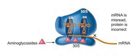
Mode of Action:
This complex group of drugs inserts itself on sites on the 30S ribosomal subunit of the prokaryotes and causes the misreading of the mRNA, eventually leading to abnormal proteins.
Figure: Site of inhibition on the prokaryotic ribosome by the drug aminoglycoside, which has a general effect of blocking the protein synthesis. The blockage action is indicated by X.
Structure of the drug:
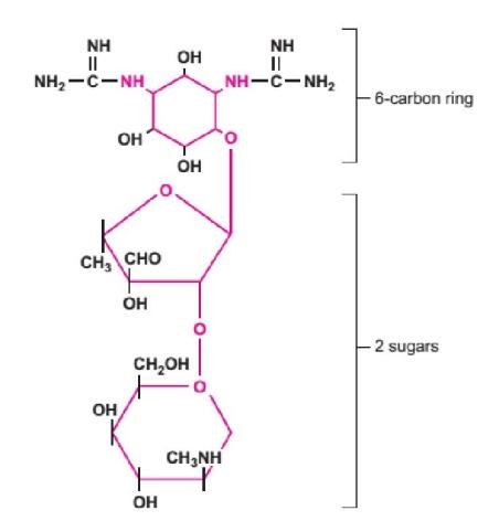
The aminoglycoside class of drugs comprises one or more amino sugars and an aminocyclitol ring, a 6-carbon cyclic ring.
Figure: The structure of an aminoglycoside: Streptomycin.
Coloured portions of the molecule are found in all members of this drug class.
Subgroups and Uses of Aminoglycosides:
The aminoglycoside group of drugs possesses a relatively broad antimicrobial spectrum since they inhibit the synthesis of prokaryotic proteins by binding to one of the ribosomal subunits. Therefore, this group of drugs is mostly used to treat infections generally caused by aerobic gram-negative rods and gram-positive bacteria.
Streptomycin is one of the oldest known drugs. However, it is gradually being replaced by newer forms of drugs that possess less mammalian toxicity. However, even today, Streptomycin is considered an effective antituberculosis agent and an antibiotic of choice for treating bubonic plague and tularaemia.
Gentamicin is less toxic and is widely administered for infections caused by gram-negative rods such as Escherichia, Pseudomonas, Salmonella, and Shigella.
Two relatively new aminoglycosides; amikacin, and tobramycin are also used for gram-negative infections, with tobramycin especially useful for treating Pseudomonas infections in cystic fibrosis patients.
Antimicrobial Resistance
Since this complex group of drugs works by blocking the protein synthesis in prokaryotes, the microbes usually circumvent these drugs by altering the nature of the protein target. Bacteria can thus become resistant to aminoglycosides when point mutations in ribosomal proteins arise.
Drug toxicity:
Aminoglycosides can directly act on the brain and cause seizures. In addition, this group of drugs may damage nerves (very commonly, the eighth cranial nerve), leading to dizziness, deafness, or motor and sensory disturbances.
Aminoglycosides such as gentamicin are nephrotoxic and are poorly cleared by damaged kidneys.
Note: The intake of other drugs must be carefully scrutinized because incompatibilities can result in increased toxicity or failure of one or more of the drugs. For example, the combination of aminoglycosides and cephalosporins increases nephrotoxic effects.
Article by- SAMPRATI PAREKH (MSIWM049)
References: Talaros Foundations in Microbiology – 8thEdition
Enzyme Inhibitor: Enzyme inhibitor decreases the rate of reaction by binding to the substrate or decreasing the turnover number. It can be organic or inorganic.
The process which decreases the rate of reaction, by either binding to enzymes or making configurationally changes is known as enzyme inhibition.
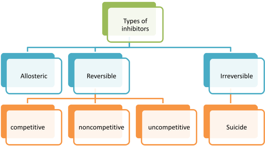
Allosteric Inhibition:
When enzyme poses allosteric side other than active site, allosteric inhibitors bind to the allosteric site causing the configuration change in enzyme, making it less feasible for enzyme to bind with substrate. This type of inhibition is partially reversible, when excess of substrate is added. Km increases and Vmax reduces.
Image source: socratic.org
Allosteric inhibition is mainly of two types
Positive allosteric inhibition: Which increases the Enzyme activity
Negative allosteric inhibition: Which decrease the Enzyme activity
Examples of allosteric inhibition
Phosphofructokinase
Activator: AMP
Inhibitor: ATP and citrate
Glycogen phosphorylase
Activator: AMP
Inhibitor: ATP
End Point inhibition: This type of inhibition is also known as Negative feedback inhibition .It is a specialized form of allosteric inhibition, which controls metabolic pathway by regulating various cellular functions. In this type of inhibition end product when formed in excess, it regulate the pathway by binding to the enzymes in reaction, thus controlling production rate.
Reversible Inhibition:
Weak interaction of inhibitor to enzyme causes reversible inhibition, which can be reverted back to normal by adding excess substrate to compete with inhibitor or by removing inhibitor. This type of inhibition follows Michaelis- Menten rate equation. It has rectangular hyperbolic curve.
Competitive inhibitor
Noncompetitive inhibitor
Uncompetitive inhibitor
When inhibitor binds to the site where substrate binds it causes competitive inhibitor
When inhibitor binds with other site except active site
When inhibitor binds with Enzyme substrate complex, It causes structural distortions
These inhibitors are mainly analogues to substrate
These inhibitors are not analogues to substrate
These inhibitors are not analogues to substrate
Vmax not changed Km increased and Velocity decreases
Vmax decreases and Km remains unchanged
Vmax and Km decreases
Example : Malonate binds Succinate dehydrogenase and competes with Succinate
Example : Ethanol binds with Acid phosphatase
Example: inhibition of placental alkaline phosphatase by phenylalanine
Irreversible inhibition:
Strong interaction of inhibitor to enzyme causes irreversible inhibition (mostly Covalent interaction). The conformation change caused in Enzyme due to inhibitor is irreversible. Enzyme activity is not regained even by adding or increasing substrate concentration. Vmax decreases and Km is not changed. Suicide inhibition is a specialized form of inhibition, which is also known as mechanism based inactivation. When inhibitor binds to enzyme, it inactivates or complete degradation of enzyme occurs. This type of inhibition does not follows Michaelis- Menten rate equation. It has sigmoidal curve.
Examples: Idoacetate , oxidizing agents etc.
Significance of Enzyme inhibition:
To study Drug action
To study efficiency of enzyme
The interaction of enzyme with substrate can be clearly understood
Elucidating cellular reactions by accumulation of intermediates
Identification of catalytic site
Various drugs used are inhibitors of reaction, so the efficiency of drug and its catalytic function can be clearly known.
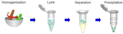
THEORY– Plant extractions for DNA is considered one of the tedious methods for high quality DNA isolations. Unlike animal tissues, which have the same tissue type in different species, plant tissues structural biomolecules and metabolites keep changing. Polysaccharides and polyphenols are two very special class of biomolecules that are very different from species to species and thus, becomes a hurdle during DNA isolation. Those biomolecules which contaminated drastically affect the manipulation of DNA isolation.
PROCEDURE-
2gm of plant sample was taken in a motor and 5ml homogenization buffer was added. Then, it was ground well for 15 minutes. Then wash it thoroughly.
15 ml of lysis buffer was added, and it was again ground well for 15 minutes.
The mixture was incubated at 65℃ for 30 minutes in microcentrifuge tubes.
The tubes were then centrifuged at 8000 rpm (rotations per minute) for 10 minutes at room temperature.
500µms supernatant was taken in microcentrifuge tube and equal volume of PCL mixture was added.
Again, tube was centrifuge at 12000 rpm for 10 minutes.
Then, the upper aqueous layer was collected (50 µL) in a new tube and chilled ethanol 200 microliter was added.
Tubes were incubated at -80℃ for 10 minutes or at 4℃ for 1hour.
Tubes were centrifuged at 12000 rpm for 12 minutes.
The supernatant was removed, pellet was air-dried and this is dissolved in µL of TE buffer.
-Submerged fermentation is a type of fermentation in which the microorganisms are suspended in a liquid medium. The liquid medium also contains various other nutrients and growth factors in the necessary proportions in a dissolved or a particulate solids form.
-Submerged fermentation is a technique in which the overall moisture content of the process is high. Therefore, it is better suited for bacteria or other microorganisms that require high moisture contents for growth.
-It is a very widely used technique for many reasons, one prominent one being that the overall purification step is much easier compared to other techniques.
-The main application of submerged fermentation technique is in the extraction of metabolites (secondary metabolites) which are needed to be in liquid form for use.
Figure 1 Overview of the process of submerged fermentation
PRINCIPLE OF SUBMERGED FERMENTATION:
-In submerged fermentation, the growth/development of the desired microorganisms occurs in the liquid environment.
-The primary substrates that are used in this technique are molasses and broth.
-The composition of the broth used is such that the proportion of the broth and the nutrients is such that the production of antibiotics, industrial enzymes etc. is optimum.
-In submerged fermentation, the rate of utilisation of the substrates is high. Therefore, the rate of depletion of them is high. For this reason, the nutrients need to be constantly replenished.
-A specific microorganism is used as the starter culture for this process. This starter organism may be fungi, bacteria or any other suitable organism. A nutrient rich broth is taken in a flask and this starter culture is then inoculated in it to begin the process.
-This technique demands high oxygen levels as the enzymes and other products are produced when microorganisms responsible for production react sufficiently with the broth and the nutrients and break them down to produce the desired products. This process requires oxygen and it is therefore an important aspect of the process.
-In the process, the compounds that are bioactive need to be secreted into the reactant broth/medium.
METHODS OF CARRYING OUT SUBMERGED FERMENTATION:
The primary two types of techniques that are used in submerged fermentation are:
Fed Batch fermentation, and
Continuous fermentation
These are discussed below:
FED BATCH FERMENATION:
In batch-fed fermentation sterilized growth nutrients are added to the culture. Fed batch fermentation is widely used in bio-industries as it helps in the increase of cell densities in the bioreactors. In these processes, the broth is usually highly concentrated to prevent or stop dilution from occurring. To maintain the culture growth rates, the nutrients are added as and when needed. Doing so, promotes the reduction of the risk of overflow metabolism.
Parameters of fed-batch fermenters:
Size- small lab scale fermenters: 1-2 L to 15 L
pilot scale fermenters: 25-100 G to2000 G
large fermenters: 5000 G to 5,00,000 G
Working volume – less than total volume as head space is left to allow to allow aeration, splashing, foaming.
Ph control – This is done by the addition of acid /alkali.
Temperature control – Heating/cooling coils are used for the temperature control inside the bioreactor. In these devices, a ‘heat transfer fluid’ is passed through the coils or the jackets of the devices which help maintain the heat equilibrium.
Agitation: – Impellor: The agitator is mounted on a central drive shaft. Impeller blades are mounted on the shaft. The blades that are used usually cover two thirds of the total diameter of the vessel.
Most batch reactors also use baffles. Baffles are immobile blades. These work by breaking up/promoting the dissipation of the flow with the help of a agitator that rotates. They are usually fixed on the inside wall of the vessel.
Aeration – Aeration is done with the help of a sparger.
–Principal modes of injecting air:
Impeller air injection—air is fed to impeller by hollow drive shaft and then injected into the medium through holes in impeller.
Two phase injection— mixture of air and nutrient medium fed in foam or suspension form
Sparger air injection– air fed by sparger orifices
Advantages: -Initial capital expenditure is lower
-It is simple and feasible to remove contamination, if any occurs during the process,
Disadvantages: – It is less effective for the production of biomass and primary (growth-associated) metabolic products.
-Batch-to-batch variability of the product
-Increased non-productive down-time, involving cleaning, sterilizing, refilling and post sterilization cooling.
-The probes and the instruments may tend to get damaged due to repeated, periodic sterilization processes.
CONTINUOUS FERMENTATION:
Continuous fermentation: An open system is constructed for continuous fermentation. In continuous fermentation, the rate of utilization of the nutrients by the microorganisms is equal to the rate of input of the externally supplied nutrients and growth factors. Due to this continuous process, a steady-rate of production is achieved.
Working mechanism: -Continuous addition of fresh fermentation medium occurs with constant stirring and agitation.
-Constant volume is maintained by incorporating an airflow weir.
-The rate of removal of broth or the spent fermentation broth is equal to the rate of addition of the fresh medium during the utilization of broth via the microorganisms present.
-There comes a stage then, where the rate at which the microbial cells grow is equal or proportionately equal to the rate at which the cells are displaced.
-The primary variables that need to be maintained to ensure the optimal production of substances using this technique include temperature, pH and gas levels (like oxygen and carbon dioxide).
SUBSTRATES USED:
The examples of the substrates used in submerged fermentation are:
Intellectual property rights (IPR) are designed to allow novel technologies to be available so that the scientist or company receives a reward for the initiative established. Intellectual property possessions can be any codified knowledge, innovation, or anything of actual or potential economic value that has arisen from rudimentary research, analysis, and manipulation of biological systems, industrial application, or for commercial use.
The various types of biotechnological inventions may be grouped into the following-
Approaches/processes of generating useful products.
Numerous products, for example- Antibiotics, vitamins, etc.
Applications of various processes/products, for example, the use of a promoter sequence to regulate gene action.
DNA sequences and the proteins.
Strains of microorganisms, cell lines are obtained by genetic modification.
Methods for genetic modification of organisms.
Patenting of Genes and DNA Sequence–
An artificially synthesized gene is patentable in almost all countries. A patented gene holds exclusive rights to the specific DNA sequence. Once patented, the holder of the patent dictates how the gene needs to be used (whether commercially or clinically) for a minimum of 20 years from the date of the patent. In the USA, genes isolated from the organisms are patentable; gene aroA (shows glyphosate resistance) isolated from a mutant bacterium was the first to be patented. For a patent to be granted in India, it should not be covered in the negative list in Section 39 which provides an extensive list of what are not the inventions under the Indian Patents Act. The act came into force in 1972 amending the Patent act,1970.
The three conditions in order to fulfil the rules imposed by Indian patent act are :
• It should be a novel creation
• It should involve an inventive step for the mankind
• There should be various industrial applications.
Ananda Mohan Chakrabarty got the first US patent for a genetically modified organism in 1981. He discovered a method for cross-linking in such a way that it fixed all the 4 plasmids to a much stabler microbe called Pseudomonas putida capable of consuming 2-3 times faster than previous strains. Its unique characteristic was hydrocarbon degradation, therefore the name was given as “multiplasmid hydrocarbon-degrading Pseudomonas”/superbug. Prof. Chakrabarty’s momentous research has since paved the way for many patents on genetically modified micro-organisms and other life forms for the coming years.
Can Life forms be patented?
The main arguments in favouring the patent of genetically modified life forms are
-They perform novel and useful functions
-They generate economic benefits
-Their production requires large financial and technical innovative inputs
However, the chief objections are usually based on ethical, moral, and religious considerations such as
-They are products of nature and hence should not be fiddled with
-Their genetic modification does not prove an industrial invention
-The inventions cause cruelty to animals
But in 1985, a patent was granted in the USA for a maize plant by overproducing tryptophan through plant tissue culture. Later, in 1988, a genetically engineered mouse called “OncoMouse” was the first mammal to be patented. It was primarily used for cancer research. The animal designed by Philip Leder and Timothy A Stewart of Harvard University used to carry a specific gene called known as an activated oncogene. The activated oncogene increased the mouse’s resistance to cancer, and thus the mouse is a promising model for cancer research. The patenting of OncoMouse, and the extensiveness of the claims made in those patents, were well-thought-out to be unreasonable by many of their colleagues. But, amid the controversies, it was finally patented in 1992.
Ultraviolet (UV) spectroscopy is an essential physical instrument that utilizes light in the electromagnetic spectrum’s ultraviolet, visible, and near-infrared ranges. The Beer-Lambert law is defined as a linear relationship between absorption, absorber concentration (or absorbing species) in the solution, and path length. Therefore, for a fixed path length, UV-Vis spectroscopy may be used to determine the absorbing species’ concentration. This is a method that is very simple, flexible, quick, precise, and cost-effective. The instrument is called the UV-Vis-NIR Spectrophotometer for ultraviolet-visible (or UV-Vis) spectroscopy. This can be used for the study of liquids, gases, and solids by using radiative energy corresponding to the electromagnetic spectrum’s far and near-ultraviolet (UV), visible (Vis), and near-infrared (NIR) regions. As a result, predetermined wavelengths have been described in these regions: UV ranges in between 300 – 400 nm, whereas visible ranges between 400 – 765 nm, and Near-Infrared ranges in between 765 – 3200 nm.
Principle: A light beam travels through an object and is determined by the light’s wavelength hitting the detector. The calculated wavelength provides valuable data on the chemical structure and the number of molecules (present in the intensity of the measured signal). Thus, it is possible to obtain both quantitative and qualitative information. Information can be obtained from a wavelength range of 160 to 3500 nm as radiation transmittance, absorbance, or reflectance. Incident power absorption promotes electrons to excited states or anti-bonding orbitals. Photon energy must equal the energy required by electrons to be promoted to the next higher energy state in order for this transition to occur. This method forms the fundamental operating theory of spectroscopy of absorption. Three types of ground-state orbitals can theoretically be involved:
1. The molecular orbital σ (bonding)
2. π (bonding) orbital molecular
3. Atomic Orbital n (non-bonding)
The anti-bonding orbitals, besides, are:
The orbital σ* (sigma star)
The orbital π* (pi star)
A transition from the s bonding orbital to the σ anti-bonding orbital involving an electron excitation is called the transition from σ to σ*. The excitation of a lone pair electron (non-bonding electron pair) to an anti-bonding π orbital is likewise expressed by π to π*. Electronic transitions that occur due to UV and visible light absorption are:
from σ to σ*;
from n to σ*;
from n to π*;
from π to π*.
Fig: Electron transitions in UV-Visible spectroscopy.
Higher energies are included in the transitions s to σ* and n to σ* and thus typically occur in far UV regions or weakly in 180 to 240 nm. Thus, in the UV zone, saturated groups do not demonstrate good absorption. Unsaturated core molecules undergo transitions n to π* and π to π*; these transitions require lower energies and thus occur at longer wavelengths than transitions to anti-bonding orbitals σ*.
Through the following types of absorption instruments, the UV-Vis spectrum can be recorded:
Single spectrometer beam
Spectrometer with double beams
Simultaneous spectrometer
All three types of spectrometers have a common light source (mostly tungsten lamps), a smallholder, and a detector. However, besides, a filter can be used to choose one wavelength at a time. This filter is also called a monochromator. A monochromator between the source of light and the specimen is part of the single beam spectrometer. For both wavelengths, the specimen is independently analyzed. The double beam spectrometer uses a single light source, a monochromator, a splitter, and a set of mirrors to direct the beam towards the reference and the sample under investigation. In contrast, a simultaneous spectrometer uses an array of diodes at all wavelengths to simultaneously detect absorbance. The quickest and most potent of the three is this.
Fig: Single and double beam UV-Visible spectrometer
Fig: Simultaneous UV-Visible spectrometer
Instrumentation: The light source (UV and visible), monochromator (wavelength selector), sample level, and detector are the essential components of a spectrometer. As a light source, a tungsten filament, continuous throughout the UV field, is usually used. Usually, the detector is a photodiode or CCD. To filter light of a specific wavelength, photodiodes go with monochromators to be fed to the detector. The visible lamp must be switched off when tracking the UV spectrum’s absorption, and vice versa. Figure 6 contains a UV-Vis-NIR Spectrometer diagram.
Components of Instrumental
A. Source of UV :
1. In its operating wavelength range, the power of the radiating source does not differ.
2. The continuous UV spectrum is created at low pressures by electrically exciting deuterium or hydrogen.
3. The UV light generation process involves creating an excited molecular species split into two atomic species and one UV photon.
4. The emission wavelengths are in the 160 to 375 nm range of both deuterium and hydrogen lamps.
5. The cuvettes’ content needs to be chosen so that the light incident is not absorbed since this would result in errors in the absorption spectrum obtained. Thus, typically, quartz is used.
B. Light Source (Visible)
1. As a visible light source, a tungsten filament lamp is used.
2. In the 350 to 2500 nm wavelength range, this lamp can produce light.
3. The energy, i.e., released, is directly proportional to the fourth power of the operating voltage in a tungsten filament lamp.
4. Thus, a highly stable voltage must be added to the lamp to achieve stable emissions.
5. By using electronic voltage regulators or constant-voltage transformers, voltage stability is assured.
6. Tungsten/halogen lamps contain small amounts of iodine, including the tungsten filament, contained within a quartz ‘envelope.’
7. The iodine reacts with sublimation-formed gaseous tungsten and creates a WI2 volatile compound.
8. They decompose when WI2 molecules touch the filament and redeposit tungsten back on the filament.
9. The tungsten/halogen lamps typically have a lifespan twice the traditional tungsten filament lamp.
10. Due to their high performance, tungsten/halogen lamps are used in modern spectrophotometers, and their output extends to the UV region as well.
C. Without Cuvettes
1. The monochromator source is used; light is separated into two sections of equal intensity by a half-mirror splitter before reaching the sample.
2. One component (or sample beam) passes through the cuvette with the material solution studied in a transparent solvent.
3. The second beam, or reference beam, passes through a comparable cuvette with only a solvent.
4. Containers of the reference and sample solution have to be transparent towards the moving beam.
D. The Detectors
1. The detector measures the light intensity emitted by the cuvette and sends it to a meter to record and show the values.
2. The strength of light beams is measured and compared by electronic detectors.
3. Two detectors have multiple UV-Vis spectrophotometers-a phototube and a photomultiplier tube, and reference and sample beams are simultaneously monitored.
4. The photomultiplier tube is the detector used widely in UV-Vis instruments.
5. It requires a photoemissive cathode (when photons strike it, electrons are released from the cathode), several dynodes (when one electron strikes it, a dynode emits several electrons) anode.
6. The photon incident hits the cathode after it reaches the tube.
7. Furthermore, the cathode releases different electrons, accelerated to the first dynode (whose potential is 90V more positive than cathode).
8. The first dynode is struck by the electrons, resulting in multiple electrons’ emission with each incident electron.
9. To create more electrons accelerated towards dynode three, and so on, these electrons are then accelerated towards the second dynode.
10. At the anode, all the electrons are finally collected. By this time, 106 to 107 electrons had been formed by each initial photon.
11. Amplified and calculated are the resulting current. Photomultipliers have rapid reaction times and are extremely sensitive to UV and visible radiation.
12. Photomultipliers, however, are only used for low-power radiation because high-power light will destroy them.
One example of a multichannel photon detector is the linear photodiode array. These detectors will simultaneously measure both elements of a beam of scattered radiation. A linear photodiode array consists of many tiny photodiodes of silicon produced on a single chip of silicon. The number of photodiodes on a chip can vary from 64 to 4096 sensor components, but 1024 photodiodes are the most common. There is a storage capacitor and a switch for each diode. It would help if you sequentially scanned the individual diode- capacitor circuits.
Fig: Photodiode array
Charge-Coupled Devices (CCDs) are like detectors for the diode series, but they consist of an array of photo capacitors instead of diodes.
The reference beam’s strength should have little to no absorption and is called I0, while the sample beam is called I. Within a short time, the spectrophotometer immediately analyses all wavelength components. In order to assess concentration as well as molecular structure or structural changes, this approach is acceptable. It is also used before and after contact with a substrate or molecule to analyze changes in vibrational and conformational energy levels.
Advantages:
1. The instrument’s precision is the most significant benefit for chemists and astronomers who use UV-VIS spectrometers.
2. Also, small UV-VIS spectrometers may provide highly accurate readings, which are essential when preparing chemical solutions or recording the celestial body’s movement.
3. It is quick to use UV-VIS spectrometers. Telescopes are connected to most UV-VIS spectrometers used in astronomy.
4. In chemistry, most of those users are similar in size to electron microscopes and require the same necessary skills to be used.
5. Since they are easy to handle, there is little risk of inappropriate use of a UV-VIS spectrometer.
Disadvantages:
1. The primary downside to using a UV-VIS spectrometer is the time it takes to plan for one to be used. Setup is vital for UV-VIS spectrometers.
2. The region must be cleared of any visible light, electronic noise, or other external pollutants that could interfere with the spectrometer’s reading.
3. UV-VIS spectrometers are easy to use and provide precise results if the room has been appropriately prepared ahead of time.
4. However, even a little bit of outside light or vibration from a small electronic device may interfere with the results you hope to achieve when using a UV-VIS spectrometer if the room has not been appropriately prepared.